Peripheral for SCOMP: Modular LED Brightness Controller with Built-In Gamma Correction
Introduction
This document summarizes the design and implementation of our custom SCOMP peripheral: a modular LED brightness controller with built-in gamma correction. Designed for clarity, flexibility, and ease of use, the peripheral allows users to set and read brightness values across an LED array using a memory-mapped Input/Output (I/O) map. Key features include a hardware-based gamma correction look-up table (LUT) and support for both individual and multi-LED control using a bit mask interface.
Our team prioritized modular design, separating functionality across control logic, brightness tracking, and gamma correction units. This approach streamlined development and made testing more efficient. The final peripheral successfully met all project specifications and closely aligned with our initial proposal goals, including the creation of a visually smooth shooting star animation and diffusion tool to demonstrate real-time control and accuracy.
Device Functionality
The peripheral supports both writing and reading LED brightness values through memory-mapped I/O registers (see Figure 1). Users interact with the device by writing values to specific addresses on the SCOMP bus, enabling precise and flexible control over an LED array.
| Address | Name | B15–B10 | B9 | B8 | B7 | B6 | B5 | B4 | B3 | B2 | B1 | B0 |
|---|---|---|---|---|---|---|---|---|---|---|---|---|
| 0x06 | LED Mask | LED9 | LED8 | LED7 | LED6 | LED5 | LED4 | LED3 | LED2 | LED1 | LED0 | |
| 0x07 | Set Brightness | 0 | 0 | 0 | Brightness | |||||||
| 0x08 | OUT Read Brightness | LED9 | LED8 | LED7 | LED6 | LED5 | LED4 | LED3 | LED2 | LED1 | LED0 | |
| 0x08 | IN Read Brightness | 0 | 0 | 0 | Brightness | |||||||
Set Brightness
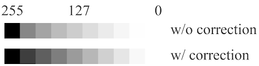
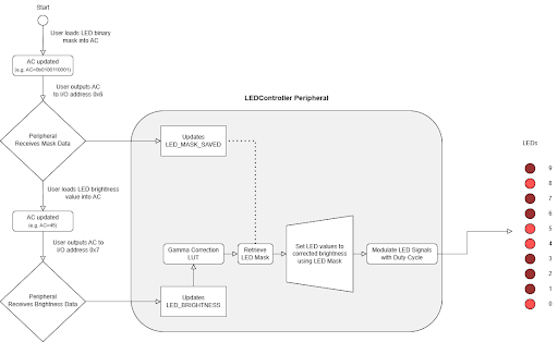
To adjust brightness, the user first writes to I/O 0x06 with a 10-bit mask in the AC. Any bit set to ‘1’ selects the corresponding LED for the upcoming operation. Next, the user writes to the I/O 0x07 with a brightness value from 0 (off) to 255 (full brightness) in the AC. After the second write, all selected LEDs will be set to the brightness value. Gamma correction is automatically applied to the brightness value (see Figure 2). This makes changes in LED brightness appear more natural to the human eye, as brightness perception is nonlinear.
Read Brightness
To read brightness, the user first writes to I/O address 0x08 with a 10-bit mask in AC with only a single bit set to ‘1’ (e.g. 0b0010000000), corresponding to a single LED. A subsequent read from the same address returns the stored brightness value (0-255) of that specific LED in AC.
Design Decisions & Implementation
We maintained consistency in the user interface by having both set/read brightness operate on a bit mask of LEDs. This allows users to control single LEDs or multiple LEDs at once. Since the bit mask consumes 10 out of 11 bits of our operand, we don’t have enough bits to also include our 4-bit brightness value. Thus, we made the trade-off to separate setting the bit mask and brightness values into separate I/O addresses.
Another key design choice was to include gamma correction using a hardware-based LUT. Implementing multi-LED control and gamma correction in hardware — rather than software — allowed for faster, more intuitive updates for the user.
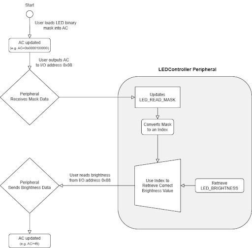
Internally, we kept the design modular by separating the LUT, control logic, and brightness tracking into different parts (see Figures 3 & 4). The LUT independently applies gamma correction to brightness values, the control logic manages I/O writes and LED routing, and the brightness module stores current values and supports state-based reading. This approach made testing easier and helped us build a more flexible, reliable system.
Conclusions
Our LED controller peripheral achieved both functional correctness and user-centric design. By offloading gamma correction and control logic to hardware, we improved ease of use and responsiveness. Future users can benefit from the clear I/O structure, state-based reading, and modular architecture for better understanding, maintainability, and expansion.
If revisiting this project, we would explore additional animation modes, increase LED count scalability, and consider integrating a software API to simplify multi-LED control even further.